Contact voltages – Protection against indirect contact

What is indirect contact?
Indirect contact
Contact with a conductive part of a device or earth which is normally de-energized and earthed, but could be energized due to a failure of the internal insulation (IEC 60050).
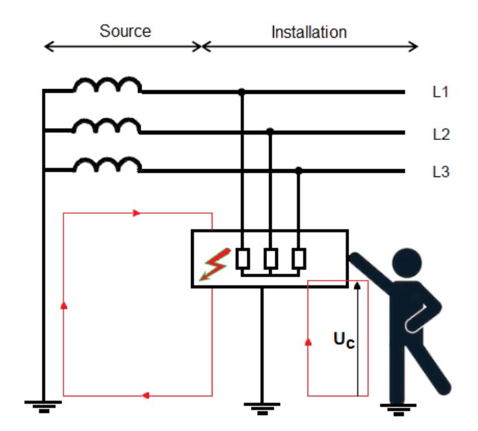
In other words, a break in the insulation of a component will generate an If fault current (see the article on calculating short-circuit currents) which will raise the ground of the faulted device to a potential that depends on the fault loop. If a person or animal comes into contact with this ground, the result can be electrification or even electrocution.
The voltage at which the faulty ground is carried is defined as follows:
- Presumable contact voltage: voltage appearing between simultaneously accessible conductive parts when these conductive parts are not touched by a person or animal (IEC 60050).
- Actual contact voltage: voltage between conductive parts when simultaneously touched by a person or animal (IEC 60050)
In practice, contact voltage is calculated between the faulty mass and earth, since cases of indirect contact between two simultaneously faulty masses are exceptional. The actual contact voltage is always lower than the presumable contact voltage, as the impedance of the person or animal in indirect contact modifies the fault loop. In the following, the term “contact voltage” (Uc) will refer to the presumable contact voltage.
The conventional contact voltage limit (or safety voltage limit) is also defined as follows:
- Conventional contact limit voltage (UL): value of the contact voltage assumed to be maintained indefinitely under specified conditions of external influence (IEC 60050)
Majority of low-voltage regulations define a safety voltage limit of:
- 50 V for alternating current
- 120 V for smooth direct current
This is the maximum permissible contact voltage for 5 seconds.
Protection against indirect contact
There are several types of protection against indirect contact:
- protection by automatic power cut-off
- protection by double or reinforced insulation
- protection by electrical separation for a single piece of equipment
- very low voltage protection
Automatic power cut-off protection measure
This protection measure is based on the combination of two conditions:
- the existence of a circuit (called a “fault loop”) to allow the fault current to flow. The composition of this fault loop depends on the earth connection diagram (TN, TT or IT). This condition implies the use of protective conductors linking the grounds of all electrical equipment supplied by the installation, so as to form the fault loop.
- the fault current is interrupted by an appropriate protective device within a timeframe that depends on certain parameters, such as the contact voltage to which a person may be subjected, the probability of faults and of contact with the faulted parts. The determination of the cut-out time is based on knowledge of the effects of electric current on the human body and the conditions of external influences. This condition implies the presence of an automatic cut-out device whose characteristics are defined according to the TT, TN or IT earth connection diagram.
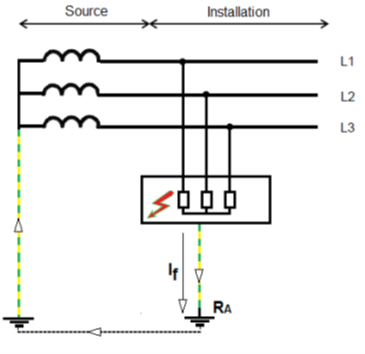
TT earth connection diagram
In this diagram, it is not possible to predetermine the fault current. This implies that the protective device is a differential device that satisfies the following condition:
𝑅𝐴 × 𝐼Δ𝑛 ≤ 50 𝑉
with
RA: resistance of ground connection
IΔn: residual differential current rating of the protective device
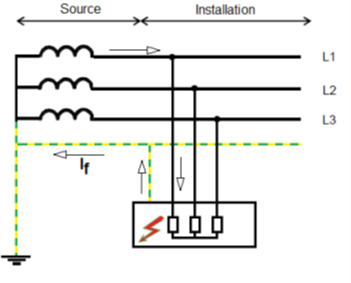
TN earth connection diagram
In this diagram, it is possible to calculate the fault current, since the fault loop comprises only active and protective conductors. The condition to be met is that the current required to operate the disconnecting device must be less than the calculated minimum fault current.
Protective devices can be overcurrent protection devices (fuses or circuit breakers) or residual current protection devices (except for TN-C).
IT earth connection diagram
In this diagram, the installation is isolated from earth or connected to earth via a high-value impedance. In the event of an insulation fault on an active conductor, the fault current is low and automatic disconnection is not necessary if the following condition is met:
𝑅𝐴 × 𝐼𝑓≤ 50 𝑉 (in alternating current)
𝑅𝐴 × 𝐼𝑓≤ 120 𝑉 (in direct current)
with
RA: resistance of ground connection
If: is the fault current in the event of a first clear fault between a phase conductor and a ground. The value of If takes into account leakage currents and the overall earthing impedance of the electrical installation.
RA x If: presumed contact voltage
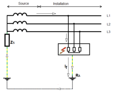
If a second fault occurs, the conditions of the TN diagram apply: the current ensuring operation of the breaking device must be less than the calculated minimum double-fault current.
Determining the maximum breaking time
The danger of indirect contact is linked to the current likely to flow through the human body, and therefore to the presumed contact voltage, as well as to the duration of exposure to this current. It is therefore necessary to check that the operating time of the switching device does not have deleterious effects. International studies on the effects of electric current on the human body have led to the definition of maximum switch-off times, which are a function of the simple voltage of the network, the earth connection diagram and the type of circuit. In the following table, IEC 60364-4-41 specifies the maximum breaking times (in sec) that must be applied to terminal circuits with a maximum rated current of:
- 63 A with one or more socket outlets, and
- 32 A supplying only fixed connected equipment
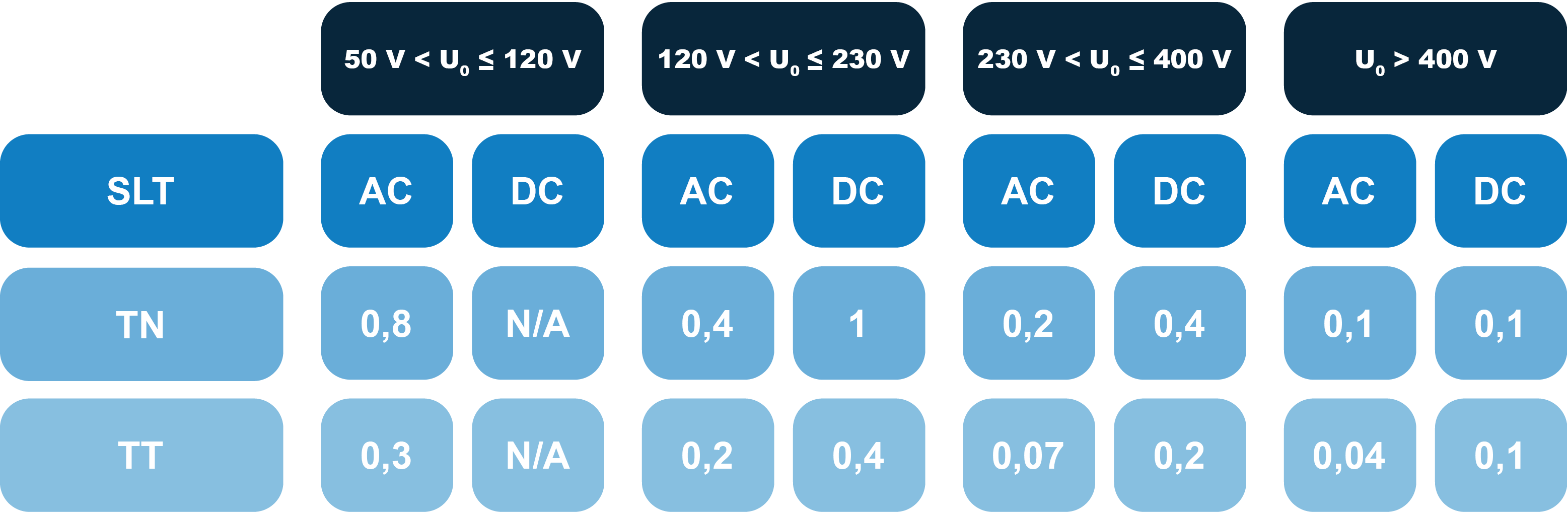
The standard IEC 60364-4-41 specifies that these breaking times apply to all terminal circuits. For other circuits, a breaking time of no more than 5 s for TN and no more than 1 s for TT is permitted. In IT diagrams, in the event of a second fault, TN diagram conditions apply.
Protection measures using double or reinforced insulation
Double or reinforced insulation is a protection measure in which:
- main protection is provided by main insulation; and insulation fault protection is provided by additional insulation, or
- main protection and protection against insulation faults are provided by reinforced insulation between active and accessible parts.
In most cases, the electrical equipment used is Class II, i.e. it must be of the following types, have undergone type testing and have been marked in accordance with the rules applicable to them:
- equipment with double or reinforced insulation (Class II equipment);
- assemblies declared in product standards as equivalent to Class II, factory-built and fully insulated.
Such equipment is marked with the symbol ![]() . Except in special cases cited in the standard, circuits supplying Class II equipment must have a protective conductor throughout, with a connection at the end of the conduit and on each accessory.
. Except in special cases cited in the standard, circuits supplying Class II equipment must have a protective conductor throughout, with a connection at the end of the conduit and on each accessory.
Protective measure by electrical separation for single equipment supply
Electrical separation is a protective measure in which protection in the event of a fault is provided by a protective separation between the separated circuit and other circuits and earth. The separated circuit must be supplied via a single separation source, and the voltage of the separated circuit must not exceed 500 V. The active parts of the separate circuit must have no common point with any other circuit, and no point connected to earth. The grounds of the separate circuit must not be connected to the protective conductor, to the grounds of other circuits, or to earth.
Extra-low voltage protection
Extra-low voltage protection is a protective measure consisting of two different types of extra-low voltage circuits:
- SELV: Separated Extra-Low Voltage
- PELV: Protected Extra-Low Voltage
For which protection is provided by:
- limitation of the SELV or PELV voltage to the upper limit of the voltage range I: 50 V AC and 120 V DC,
- protective separation between SELV or PELV circuits and all other circuits other than SELV or PELV, and main insulation between SELV and PELV circuits and other SELV or PELV circuits,
- for SELV circuits only, main insulation between the SELV circuit and earth.
For the implementation of this protection measure, please refer to the corresponding paragraphs of the standards. (IEC 60364-4-41 §414).
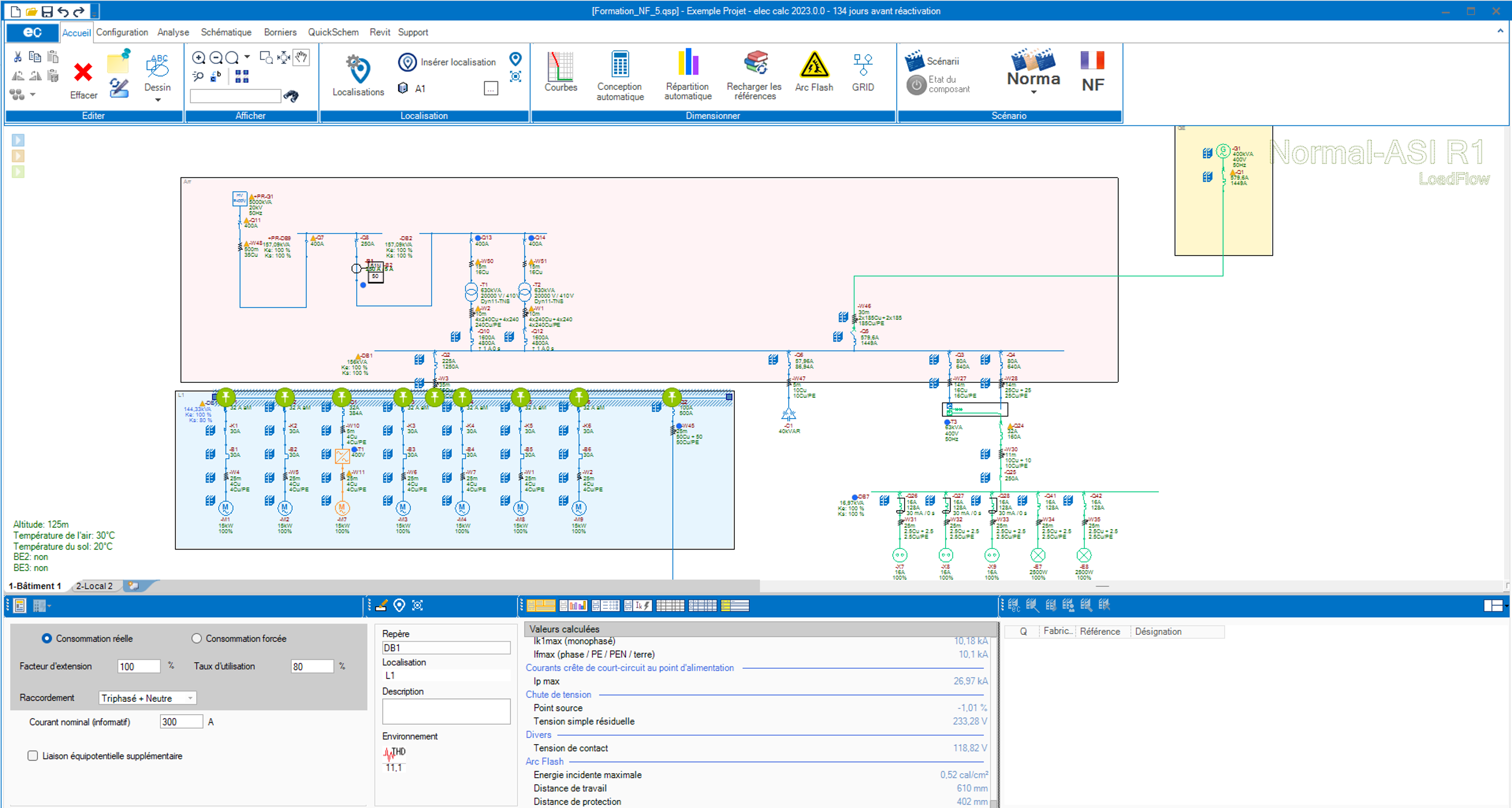
Checks with elec calc™
Management of contact voltages
elec calc™ checks that the operating time of protections remains below a certain value, depending on the contact voltage. This contact voltage is the voltage that can be established between a device’s ground and earth in the event of a phase-to-ground fault. It is therefore calculated from the phase/earth short-circuit current If.
Do you want to know more about our electrical calculation software?