Diseñar, gestionar, innovar:
software para edificios sostenibles
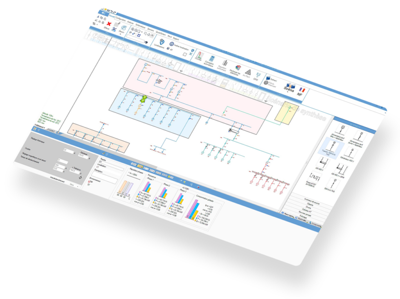
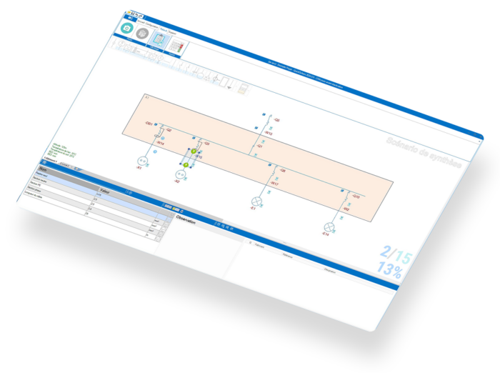
Software de modelado y gestión eléctrica, fotovoltaica, energética y ambiental.
Un paquete completo de software
Filtrar por :
Electricidad
Solar


Electricidad
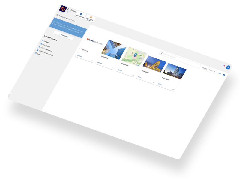
Gestione sus proyectos de elec calc en línea con diferentes partes interesadas


Electricidad
Gestione sus proyectos de elec calc en línea con diferentes partes interesadas


Electricidad
Gestione sus proyectos de elec calc en línea con diferentes partes interesadas


Software para cada fase de su proyecto:
Operación y Mantenimiento
Confían en nosotros y hablan de ello


"La integración del hardware de los fabricantes y la precisión del software nos permitieron entregar un estudio preciso que destacó la necesidad de reemplazar los equipos existentes y así garantizar la continuidad del funcionamiento del edificio."
Lionel Pereira
Diseñador industrial, oficina de diseño Swissohm
Diseñador industrial, oficina de diseño Swissohm
"La herramienta elec calc es versátil y admite alta y baja tensión en el mismo proyecto, lo cual es un punto fuerte."
Alexandre Rondeau Director de la oficina de diseño SPIE Nucléaire
"Los clientes absorben los resultados y, en general, esperan con interés su inversión. archelios PRO es una herramienta de marketing que ayuda a cerrar ventas."
Thomas Lecaille
Director de SUNPV CONSULT
Director de SUNPV CONSULT
"archelios PRO es compatible con SketchUp, lo cual es muy importante para nosotros porque podemos producir simulaciones muy detalladas con un alto nivel de gráficos. El software permite un gran margen de personalización, lo que en general es muy apreciado por nuestros clientes, ya que ven que el estudio presentado es realmente suyo."
Olivier Verdeil
Experto en energía solar del INES
Experto en energía solar del INES
"En elec calc es muy fácil gestionar varios modos de funcionamiento en una misma instalación así como varias fuentes."
Yann Le Saout
Study manager, Actemium
Study manager, Actemium
"elec calc GRID nos ha ayudado a hacer el dimensionamiento eléctrico de una manera más ágil y completa."
José Luis Gómez
Director Técnico de AEON
Director Técnico de AEON
"Pudimos retomar casi quince años de trabajo en nuestras instalaciones, que queríamos mantener y seguir desarrollando. Todos nuestros archivos han sido procesados en el nuevo software y ahora que hemos recibido capacitación, podemos continuar desarrollándolos con tranquilidad."
Jean-Christophe Gandon
Director Técnico - Departamento EIA - Oril Industrie, Grupo Servier
Director Técnico - Departamento EIA - Oril Industrie, Grupo Servier
"Con la funcionalidad 3D MAP de archelios PRO, puedo ofrecer una oferta económica a un cliente sin tener que ir primero al sitio. También ahorra tiempo y dinero."
Quentin Wattiez
Director de desarrollo fotovoltaico de Equans Ineo
Director de desarrollo fotovoltaico de Equans Ineo
"Con Trace Software asistimos a una presentación realizada con un enfoque muy didáctico. Se entendió nuestro problema y pudimos descubrir un software moderno y ergonómico con un enfoque relevante para nuestras necesidades."
Alexandre BODET
Director asociado de B2E
Director asociado de B2E
Nuestros compromisos
Atención al cliente reactiva
Soluciones actualizadas regularmente
Apoyo en su transición energética
Software con un diseño ergonómico

¿Saber más de nuestras soluciones?
Suscríbase a nuestro boletín
Artículos regulares sobre nuestros avances, nuestras soluciones y nuestra industria.
Una solución a la medida de los expertos

Instalador
Nacional
Regional
Industria
Terciario
Pequeño sector terciario
Nuclear
Petroquímica
Farmacéutico


Adjudicación
Industria
Terciario
Privado
Público
Consultoría pequeña y mediana
Gran consultoría
Ejecución
Concepción


