


 Technical
Figure 1: Table G52.1 – Extract from the IEC 60364-5-52 standard
Different approaches can be used to assess the voltage drop according to the desired accuracy.
Approximate formula (IEC 60364-5-52)
This formula is suitable for single-phase, two-phase and three-phase balanced circuits with a power factor greater than 0.8:

Figure 2: Mathematical formula for voltage drop according to IEC 60364-5-52
Vector method (AFNOR FD C 15-500)
This more precise approach is based on a vector representation of the voltages and currents in the pipeline. However, it does not take into account any imbalances in three-phase circuits.

- U1: Single or compound tension originally from the cable
- U2: single or compound tension at the end of the cable
- φ: phase shift of the current in the cable
- Z: Cable impedance = √R2+X2
- R: cable resistance = ρ1LS
- X: cable reactance = λL
u=U1+IbRcosφ+IbXsinφ−√U12−(IbXcosφ−IbRsinφ)2
The equivalent voltage drop in percentage is:
- For three-phase and single-phase circuits Δu=100uU0
- For two-phase circuits Δu=100uU0√3
- U0: nominal voltage between phase and neutral in volts
Detailed method
For an accurate calculation of voltage drops, the exact method is to calculate the residual voltage (modulus and phase) at any connection point of the installation and for each conductor.
In the case of a single-source installation, a sequential calculation on each cable section makes it possible to arrive at the result by taking into account the impedances of each conductor and the currents passing through each of these conductors. The real voltage drop in % is calculated by comparing the lowest voltage modulus at the receiver power point and the voltage modulus at the origin of the installation.
In the case of installations with several sources that are intended to supply the grid simultaneously, the calculation is very complex and involves iterative matrix calculation methods (load flow calculation).

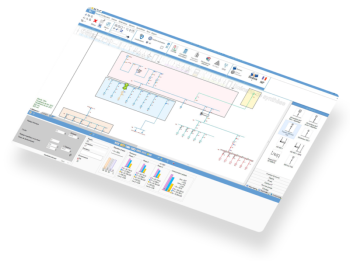
Figure 4: Analysis of voltage drops on an electrical network with elec calc
Managing transformers and adjusters in elec calc
A voltage regulator or tap changer allows the voltage of a transformer to be adjusted according to changes in the network or load.
elec calc simulates three scenarios:

- Without adjuster → Addition of the voltage drops of the upstream network, the transformer and the downstream network. This will make it possible to obtain the exact residual voltage at the level of each receiver.
- De-energized adjuster → Adjusting the no-load voltage to the secondary of the transformerThis device makes it possible to overcome the difference between the actual voltage of the upstream network and the assigned primary voltage of the transformer. This adjustment is generally made when the transformer is put into service in order to obtain the no-load voltage assigned to the secondary of the transformer.
- Load Adjuster → Suppression of the transformer’s internal voltage drop regardless of the downstream load.

Figure 5 : Effet des régleurs de tension sur la chute de tension
Learn more about our solution![]()

Jérôme MULLIE
Technical Director - Trace Software
In addition to providing a complete calculation solution, we also want to share our expertise in electrical engineering with the players in the sector in order to support them in the design and operation of their installations.