


 Technical
Summary
An earthing system defines the relationship between the neutral point of the supply and earth, and the connection between the exposed-conductive-parts of an installation and earth. In the UK, this is governed by BS 7671:2018+A2:2022 (the IET Wiring Regulations, 18th Edition), which implements the IEC 60364 series, together with the Electricity Safety, Quality and Continuity Regulations 2002 (ESQCR), which sets out the earthing arrangement a Distribution Network Operator (DNO) must offer at the point of supply. Earthing system selection directly determines the choice of protective devices, conductor sizing and how an installation behaves under an earth fault.
The four base systems are TT, TN-C, TN-S and IT. In UK practice, TN-C only ever appears on the supply side of the origin: within a consumer’s installation, BS 7671 Regulation 543.4.1 prohibits the use of a PEN conductor. What most UK properties actually have is TN-C-S, universally referred to as PME (Protective Multiple Earthing) — TN-C from the transformer to the supply cut-out, TN-S from that point onward. In installations with multiple sources, the coexistence of different earthing arrangements calls for a careful review of every switching state and of the consistency of the protective devices across each state.

Reference Table
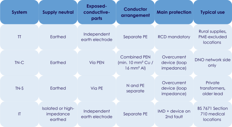
Earthing systems: selection criteria, protective devices and BS 7671 references
Download the tableThe parameter that shapes the whole electrical design
A circuit-breaker that fails to trip on an earth fault. Residual voltages appearing on metallic enclosures. An Electrical Installation Condition Report (EICR) that flags a non-conformity without an obvious cause. In most of these cases, the root cause traces back to the earthing system: it was misidentified, it was applied without regard to the protective devices installed, or it got mixed with a different arrangement during an extension.
The earthing system is not a secondary parameter. It is the first technical decision that shapes a low-voltage installation. It determines the level of fault current on an earth fault, the protective measures required, and the conditions under which BS 7671 considers people to be adequately protected.
This article covers the four principal earthing systems, explains the differences between TN-C and TN-S, addresses the transition between systems, and looks at multi-source installations an area that standard calculation tools often don’t cover in full.
Designing installations with several sources of supply? Find out how elec calc handles earthing systems in multi-source configurations. Request an elec calc demo.
Reading the system code like an engineer
What each letter means
The IEC 60364 series (section 312.2), implemented in the UK through BS 7671:2018+A2:2022, uses a two- or three-letter code. The logic is precise and worth learning properly, since it appears throughout technical documentation, design software, and correspondence with Building Control and DNOs.
- The first letter describes how the supply neutral point relates to earth. T means the neutral is earthed directly. I means it is either isolated from earth or connected to it through a high impedance.
- The second letter describes how the exposed-conductive-parts of the installation relate to earth. T means the exposed-conductive-parts are connected to an earth electrode independent of the source earth. N means they are connected to the earthed neutral of the source itself.
- When the second letter is N, a third letter defines how the neutral and protective functions are arranged.
- C (Combined) means the neutral and protective functions are combined in a single conductor, the PEN (Protective Earth and Neutral) conductor.
- S (Separate) means they are kept physically apart: an N conductor carries the return current, a PE conductor provides protection.
This is also how TN-C-S / PME is best understood: TN-C upstream, as far as a single point where the PEN conductor is split; TN-S from that point downstream. This is the arrangement used for the vast majority of UK domestic and light commercial supplies.
TT: the fallback arrangement where PME cannot be used
In a TT system, the transformer neutral is earthed at the substation, and the exposed-conductive-parts of the installation are connected to the customer’s own earth electrode, independent of the supply earth.
On an earth fault, the fault current returns through both electrodes, and its magnitude depends on their combined resistance. It is generally too low to trip an overcurrent device within the disconnection times required by BS 7671. This is why an RCD (residual current device) is essential for fault protection in a TT system: it detects leakage current to earth, typically operating at 30 mA on final circuits.
In the UK, DNOs use TT where PME cannot safely be offered for example, in rural areas served by overhead lines, or for installations covered by Sections 708 (caravan/camping parks), 709 (marinas) and 717 (mobile/transportable units) of BS 7671, where PME earthing must not be exported. TT is straightforward to install and well suited to installations where an independent local earth is the safer or only practical option.
IT: when continuity of supply matters more than anything else
In an IT system, the supply neutral is either isolated from earth or connected to it through a high impedance, typically a few kilohms. On a first insulation fault, the resulting fault current is very small and the installation carries on running. An insulation monitoring device (IMD) detects and signals this first fault, allowing it to be traced and cleared without an outage.
The danger appears on a second, simultaneous fault on a different conductor: at that point the situation is equivalent to a fault between live conductors, and the protective device must operate. This is why an IT system demands active maintenance, trained personnel, and a prompt response to IMD alarms.
In the UK, IT systems are specified where BS 7671 Section 710 applies Group 2 medical locations such as operating theatres and critical care areas and in certain continuous industrial processes. It is not appropriate for unsupervised installations.
TN-C and TN-S: the differences that matter on site
TN-C: a supply-side arrangement, not an option within the installation
In a TN-C system, a single PEN conductor carries both the neutral current and the protective function. This reduces conductor count and was common in industrial distribution networks built between the 1970s and 1990s.
Under BS 7671, TN-C has no place within a consumer’s installation: Regulation 543.4.1 prohibits the use of a PEN conductor downstream of the origin, except in the very limited circumstances set out in Regulation 543.4.2. Where a PEN conductor does exist on the distributor’s network, up to the supply cut-out it must not be smaller than 10 mm² copper or 16 mm² aluminium.
The reason for this restriction is the risk posed by an open-circuit PEN. If the PEN conductor breaks upstream of a consumer’s installation an “open-PEN” fault the combined neutral/earth terminal, and everything bonded to it, can rise to a dangerous potential relative to true earth. This risk is very difficult to detect during normal operation and is the reason UK guidance increasingly asks installers to consider open-PEN protection, particularly for PME-supplied installations feeding equipment outdoors, such as EV charge points.
TN-S: the reference arrangement for modern installations
In a TN-S system, the neutral (N) and protective (PE) conductors are physically separate throughout and perform distinct functions. The PE conductor stays at earth potential at all times, independent of any disturbance on the neutral.
On a solid earth fault, the fault current returns to the source through the PE conductor at a high magnitude, allowing the protective device to disconnect quickly provided the loop impedance is low enough, which BS 7671 requires to be verified at the design stage (the disconnection condition Zs × Ia ≤ Uo, Regulation 411.4.4).
TN-S remains the reference arrangement for private supplies with their own transformer and for installations where a genuinely separate protective conductor is required throughout. Verifying it properly means calculating loop impedances rigorously, which is where dimensioning software earns its keep.
From TN-C to TN-S (or PME to a separate installation earth): a one-way operation
Where a PEN conductor is split typically at the origin of the installation, at the main intake position or a sub-distribution board it is divided into a separate N bar and a separate PE bar, with a single bonding link at that one point only. Downstream, the two conductors must remain strictly separate.
This separation is irreversible in normative terms: N and PE must never be rejoined anywhere downstream of the split point. This rule is absolute. During extensions or alterations to existing installations, wiring errors sometimes reintroduce an unintended N-PE link in a sub-board. The consequences are hard to diagnose and present a genuine risk to people.
Points to check when carrying out this kind of work:
- Confirm that downstream cables include a properly sized, separate PE conductor.
- Confirm the PE bar is correctly connected to the installation’s means of earthing.
- Record the split point in the installation’s design records and O&M documentation.
- Check every downstream distribution board for an unintended N-PE bridge.

Excel Template
Earthing systems: selection criteria, protective devices and BS 7671 references
Dowload the full reference tableMulti-source installations: when earthing systems don’t match
A growing source of complexity in commercial and industrial buildings
Modern installations increasingly combine several sources of supply: the DNO network, a standby generator, an uninterruptible power supply (UPS), a power inverter, battery storage (BESS), and sometimes on-site solar generation. Each of these sources can, in principle, operate on a different earthing system.
A typical case: a normal supply on PME (TN-C-S), paired with a standby generator running TN-S with its own local earth electrode. On automatic transfer, the difference in potential between the two earths can drive circulating currents, disturb RCDs, or cause nuisance tripping on sensitive equipment.
The central question in these configurations is how the neutral is handled during transfer. Several strategies are possible depending on the architecture chosen: switching with a clean neutral break (4-pole changeover), a synchronised neutral switch, or a neutral shared across all sources. Each has direct consequences for protective device selection and for verifying discrimination and disconnection times in every operating state.
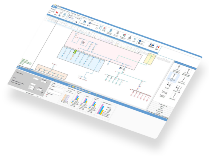
This kind of analysis is generally beyond the reach of standard calculation tools, which typically assume a single source on a single earthing system. This is precisely what elec calc addresses: version 2026.1 supports the modelling of mixed TN-C/TN-S earthing arrangements in multi-source architectures, with automatic verification of protective device compliance in every network state normal supply, standby generator, UPS, battery storage. The resulting report can be used directly in the technical file.
The most common design errors
1. Applying the network operator’s earthing system to the whole installation
Where an industrial site is fed from its own HV/LV transformer, the LV earthing system is a design choice, not something imposed by the network. Treating the DNO’s TT arrangement as if it applied to a privately owned transformer leads to protective devices selected for the wrong earthing system.
2. Undersizing the PEN conductor where TN-C genuinely exists (on the network side)
Modifications or extensions carried out without recalculation sometimes leave a PEN conductor below the 10 mm² copper minimum. An undersized PEN conductor may fail to clear a fault within the required time and presents a thermal risk under fault conditions.
3. Creating an N-PE bridge downstream of the PME split point
This is the hardest fault to detect after the fact. It typically arises during an extension carried out by a different contractor from the one who designed the original installation, or when a distribution board is replaced and the separate N and PE bars aren’t kept apart. The installation works normally day to day, but its behaviour under fault becomes unpredictable.
4. Not recalculating loop impedance after a change
Every extension to a TN-S circuit lengthens the fault loop and increases its impedance. If this isn’t recalculated, the disconnection condition may no longer be met on the circuits furthest from the source invisible in normal use, but a real problem under fault.
Earthing systems compared
FAQ
In TN-C, the neutral and protective functions share a single PEN conductor. In TN-S, they’re kept separate: N carries the return current, PE provides protection. TN-S is inherently safer, because a break in the neutral doesn’t affect the protective conductor. Under BS 7671, a PEN conductor is not permitted within a consumer’s installation (Regulation 543.4.1) which is why every UK installation is, in effect, TN-S downstream of the origin, whether the incoming supply is PME, TN-S or TT.
The split happens at a single point, usually the intake position: the incoming PEN conductor is divided into a separate N bar and a separate PE bar, with one bonding link at that point only. Downstream, N and PE must stay strictly separate this is irreversible. It’s worth confirming that downstream cables carry a proper separate PE conductor and that the split point is recorded in the installation’s documentation.
The four systems are TT (earthed neutral, independent earth electrode), TN-C (earthed neutral, PEN conductor), TN-S (earthed neutral, separate PE) and IT (isolated or high-impedance neutral, independent earth electrode). TN-C-S universally known in the UK as PME combines TN-C upstream and TN-S downstream within the same network, and is the arrangement behind most UK domestic and commercial supplies.
Yes, within limits. The most common case is PME itself. Beyond that, an installation may need to depart from the incoming PME earth for specific locations outbuildings with a bath or shower, or locations covered by BS 7671 Sections 708, 709, 717 and 722 (EV charging) where a local TT arrangement, or PEN-fault detection built into the equipment, is required instead. In multi-source installations, coexisting arrangements are possible but require a full review of every switching state and its protective devices.
Directly. On a TN system, verifying the disconnection condition Zs × Ia ≤ Uo (BS 7671 Regulation 411.4.4) means checking conductor size and length to guarantee automatic disconnection. Main bonding conductor sizing also depends on the earthing system: PME (TN-C-S) supplies require larger main bonding conductors, sized to the supply PEN conductor via Table 54.8, than TN-S or TT supplies (Regulation 544.1.1).
Conclusion
The earthing system is the first technical parameter of a low-voltage installation. Its selection shapes the entire protection strategy, drives conductor sizing, and determines how the installation behaves under fault. A well-designed installation on this point satisfies Building Control and third-party certification, protects people, and stays easy to extend.
Multi-source configurations add a further layer: each source can bring its own earthing arrangement, and every transfer between sources creates a distinct network state that has to be checked in its own right.
elec calc is built for that reality, with native modelling of mixed TN-C/TN-S earthing arrangements across multi-source architectures, and a compliance report ready for the technical file. elec calc also holds Gimelec ELIE BT 2025 certification, confirming that its calculation methods meet current standards.
This article was written by :

Fabien LEROY
Product Expert - Trace Software
Beyond providing an increasingly comprehensive electrical calculation solution, we also aim to share our technical and industry expertise with stakeholders in the sector, in order to support them in sizing, validating, and ensuring the consistency of the generated calculation reports, thereby guaranteeing their accuracy and operational relevance.


