


 Technical
Summary
Thermal stresses in an electrical conductor correspond to the heating experienced by a cable during a short circuit. For a fault elimination time of less than 5 s, the adiabatic hypothesis and the relation I²t ≤ k²S² are used to verify that the through-energy does not exceed the permissible thermal resistance of the conductor. This article explains the concept, common errors, a step-by-step method with calculations, and the solutions (oversizing, fuses, circuit breakers) to remain compliant and protect the installation in the long term.
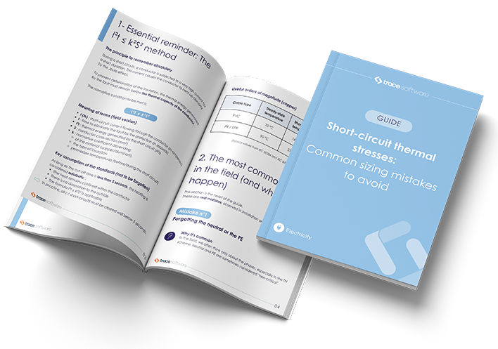
You want to have a perfect command of thermal stress verification to avoid damaging your cables in the event of a short circuit
This guide is for you!
Download the guideIntroduction
When a short-circuit current passes through a conductor, even for a very short time, it causes a rapid rise in temperature. If this rise exceeds the permissible temperature of the conductor (core + insulation), the cable can be damaged, with immediate consequences (insulation defect, breakage, repeated tripping) or delayed consequences (premature ageing, embrittlement).
International fire safety studies consistently show that a significant proportion of building fires are of electrical origin, highlighting the importance of proper electrical design and protection. The ONSE also highlights significant volumes of claims and damage associated with electricity.
From design to operation, the challenge is therefore to prove, with calculations, that the thermal stresses generated in the fault remain compatible with the behaviour of the conductors. The question to be solved is simple in its formulation, but requires rigour in execution: how to verify that the thermal stresses remain compatible with the performance of the conductors, in all fault situations?
Understanding the phenomenon: why does a conductor short-circuit?
The thermal effects of electric current (Joule effect)
Any current in a conductor dissipates some of the electrical energy as heat. The greater the intensity, the faster the heating increases (proportional to I²). In a short circuit, the intensity can reach several kiloamperes: the heating then becomes sudden.
Adiabatic hypothesis: the basis of calculations
For a fault removal time of less than 5 seconds, the heating is generally considered to be adiabatic : the heat produced remains essentially in the conductor’s core, without having time to dissipate to the insulation and the environment.
The two values you need to know to correctly size a conductor
To correctly size a cable, two normative temperatures structure the reasoning:
- The maximum temperature of the web in steady state (useful for calculating the ampacity current).
- the maximum permissible temperature of the short-circuited core, corresponding to the threshold beyond which the insulation begins to deteriorate and the cable is no longer guaranteed.
For standard cables, these values are imposed by the standards. For example, for PR/EPR insulated cables, a maximum temperature of 90 °C in steady state and 250 °C in short circuit is classically found.
Through energy and permissible thermal stress: the verification logic
The verification is based on the comparison of two quantities:
- Through energy (I²t): the energy dissipated by the short circuit in the conductor during the duration of the fault.
- The permissible thermal resistance (k²S²): the maximum thermal capacity that the conductor can withstand without exceeding the permissible temperature.
The objective is to verify that the energy generated by the fault remains below the thermal capacity of the conductor.
Thermal stresses do not forgive approximations.
Find out the most common mistakes in the field and how to avoid them in practice.
Formulas: How to Calculate a Short-Circuit Thermal Stress
1) Calculation of the energy through
Under adiabatic hypothesis, the through-energy is calculated with:
- Energy through = Ik² × t (in A²s)
Where:
- Ik is the short-circuit current (in A),
- t is the time to eliminate the defect (in s).
2) Calculation of the permissible thermal resistance of the conductor
The permissible thermal stress is calculated with:
- Permissible thermal resistance = k² × S²
Where:
- S is the cross-section of the conductor (in mm²),
- k is a factor taking into account the resistivity of the material, the temperature coefficient, the initial and final permissible temperatures.
The values of the k-coefficient are provided by standardized tables, notably in IEC 60949 and IEC 60364-5-54.
3) Condition to be met
Verification consists of ensuring that: Ik² × t < k² × S²
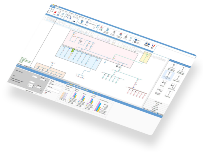
Checking through energy in practice with elec calc
In the field as well as in the design office, the verification of thermal stresses can quickly become tedious as soon as the installation includes several feeders, different conductor sections or protections with varying behaviors. It is precisely in this context that the automation of calculations takes on its full meaning.
The elec calc software allows the automatic verification of the through-flow energy on all the conductors of the installation. For each cable, the software calculates the maximum energy transmitted during a short circuit and then compares it directly to the permissible thermal resistance of the conductor, according to the normative relationship k² × S².
This verification is not limited to phase conductors. It also applies to neutral and protective conductors (PE), in accordance with IEC 60364 requirements. If the condition Ik² × t < k² × S² is not met, elec calc explicitly reports a thermal stress error on the cable in question, which makes it possible to immediately identify the point to be corrected.
This approach ensures a complete and consistent design, even on complex or multi-start installations, where a manual calculation becomes a source of errors or omissions.
Example of calculation: Highlighting a thermal stress problem
Consider an installation with a lighting circuit powered by a 2.5 mm² XLPE insulated copper cable, protected by a 16 A C-curve circuit breaker.
The maximum short-circuit current at the cable is 5.63 kA, and the protection trip time is 10 ms.
The maximum energy through is therefore:
Ik² × t = 5,630² × 0.01 = 316,969 A²s
The permissible thermal resistance of the cable is calculated with:
k² × S² = 138² × 2.5² = 119,025 A²s
The relationship is not respected. There is therefore a problem of thermal stress : in the event of a short circuit, the cable will be damaged.
How to Fix a Thermal Stress Problem
Increase the conductor cross-section
The most direct solution is to increase the cross-section of the conductor, which mechanically increases its permissible thermal resistance. This approach is effective, but it can be costly and restrictive, especially in renovation.
Use Fuses
The melt time of a fuse is usually much shorter than the time of a circuit breaker open for high short-circuit currents. This results in a natural limitation of the energy flowing.
In the previous example, by replacing the circuit breaker with a gG 16 A fuse, the meltdown time is 4 × 10⁻⁵ s. The energy passing through then becomes:
Ik² × t = 5,630² × 0.00004 = 1,268 A²s
The thermal constraint is now respected.
⚠️ Caution : With a fuse, the maximum energy can sometimes appear for a minimum short circuit. It is therefore essential to check all fault scenarios.
Use limiting circuit breakers
Some ranges of circuit breakers are designed to limit the energy transmitted to the circuit. Manufacturers provide limiting curves for this, in particular limited through-energy curves.
Analysis of limitation curves with the elec calc multi-manufacturer catalog
The multi-manufacturer catalog integrated into elec calc makes it possible to directly exploit the protection limitation curves. As soon as a hardware reference with limiting capability is associated with protection, the software automatically recovers the residual energy corresponding to the assumed short-circuit current.
In the example studied, for a current of 5.63 kA, the residual energy read on the curve is 15,250 A²s, a value lower than the permissible thermal resistance of the cable. The thermal stress problem is therefore solved without modifying the cross-section.

Going further with elec calc: precision calculations
For complex installations, elec calc allows you to go beyond the simplified approach.
The software takes into account the influence of the DC component of the short-circuit current when required by the standard used, in particular according to the X/R ratio and the fault elimination time.
It also integrates the case of multiple sources, by making a chronological accumulation of the energies produced by each source according to the actual behavior of the protections. This approach makes it possible to get as close as possible to the real phenomenon and to avoid any underestimation of thermal stresses.
FAQ
What are the thermal effects of electric current?
The current causes heating by the Joule effect. In short circuits, the very high current causes the conductor temperature to rise rapidly.
Why does an electric conductor heat up?
Because it has an electrical resistance: part of the energy is transformed into heat. The more the intensity and duration increase, the greater the warm-up.
What is the formula for thermal stresses?
Under adiabatic hypothesis (elimination time less than 5 s), we verify: Ik² × t < k² × S².
What to do if the thermal stress is not respected?
The main options are: use a limiting circuit breaker (reduction of the residual energy transmitted), use a fuse (reduction of time and therefore of through-energy), or increase the cross-section of the conductor.
Should you check only the maximum short circuit?
Not always. With fuse protection, the maximum energy can appear with minimal short circuit if the melting time becomes longer. It is therefore necessary to check several scenarios
Conclusion
Checking the thermal stresses in an electrical conductor is equivalent to comparing the through-energy (Ik²t) to the permissible thermal resistance of the conductor (k²S²). As long as the through-flow energy remains below the permissible resistance, the conductor can withstand the fault without exceeding its maximum short-circuit temperature.
By automating these checks and faithfully integrating the normative and manufacturer data, elec calc makes it possible to apply the principles set out in this article in a concrete and reliable way, even on complex installations.
Do you want to automatically check the thermal stresses of your installations?
Contact us to find out how elec calc secures your sizing calculations.
This article was written by:

Jérôme MULLIE
Technical Director - Trace Software
In addition to providing a complete calculation solution, we also want to share our expertise in electrical engineering with the players in the sector in order to support them in the design and operation of their installations.