


 Technical
Designing a photovoltaic installation and its electrical network within a single calculation software: this is what professionals refer to as the unified approach. This scope covers everything from PV modules through to alternating current uses, EV charging infrastructure, and grid connection.
Fragmented methods require working across multiple tools. The unified approach simultaneously models both the DC side and the AC side within a single environment.
For engineering firms and installers, this improves the reliability of calculation reports and reduces the risk of non-compliance with IEC 60364-7-712. It also provides a living technical reference throughout the entire lifecycle of the installation.
1. Why the photovoltaic market requires a new approach
The photovoltaic market is experiencing sustained growth. According to electricity market data for 2025, installed photovoltaic capacity reached 30.4 GW at the end of 2025, compared to 20.4 GW at the end of 2023, representing growth of nearly 50% in two years. Energy development targets aim for 48 GW by 2030 and between 55 and 80 GW by 2035.
This acceleration is creating increasing technical challenges for system designers:
• Growth in projects on buildings, car parks, and canopies
• Integration of solar generation into existing electrical networks
• Expansion of collective self-consumption and hybrid systems
• Coexistence with new energy uses such as EV charging infrastructure and energy storage
In this context, sizing a solar installation without simultaneously modelling the electrical network inevitably leads to inconsistencies. Engineering teams must ensure that installations remain reliable, efficient, and compliant, which requires a global view of the project from the design stage onward.
Photovoltaic projects are governed by:
• IEC 60364-7-712, which defines requirements for photovoltaic installations
• General low-voltage electrical installation rules
• Grid connection requirements defined by network operators
According to international technical references, IEC 60364-7-712 is the main standard for designing grid-connected PV systems. The challenge for designers is therefore not only to size solar production, but to ensure consistency across the entire electrical system.
2. What is unified photovoltaic sizing?
Unified photovoltaic sizing consists of modelling, within a single calculation environment, the entire electrical infrastructure associated with a photovoltaic installation. This approach covers:
• Photovoltaic modules and DC strings
• Inverters and their MPPT inputs
• Low-voltage distribution boards
• Grid connection and any associated transformers
• Electrical uses on site: buildings, industrial processes, EV charging
The objective is to work with a single electrical model in which the photovoltaic installation and the distribution network are analysed simultaneously. Any technical modification—such as a change of inverter, an increase in power, or the addition of a new load—immediately propagates across all calculations:
• Cable cross-sections
• Electrical protections and surge protection devices
• DC and AC voltage drops
• Transformer sizing
• Power flows within the network
This continuity of calculation is what fundamentally differentiates the unified approach from fragmented methods. A single change is enough to update the entire study.
3. The limitations of fragmented sizing
In many photovoltaic projects, design is still based on a separation between solar studies and electrical studies. The photovoltaic system is sized using a dedicated production tool, while the electrical design is carried out in a separate software environment.
This approach introduces three major risks.
Data re-entry
Cable lengths, equipment characteristics, and power values must be entered again in each tool. A simple input error can create significant discrepancies in calculation results.
Inconsistent technical assumptions
Parameters used for the photovoltaic model are not always reproduced identically in the electrical study. Operating temperatures, cable installation methods, or circuit grouping may differ from one model to another.
Complex change management
When an installer changes the inverter model or increases the PV capacity, multiple studies must be updated independently. These practices can lead to gaps between the design and the actual installation on site.
4. Regulatory compliance: continuous verification
Regulation is a central component of photovoltaic system design. Electrical installations must meet strict requirements in terms of safety, performance, and dimensioning.
IEC 60364-7-712 complements general electrical rules by defining requirements specific to photovoltaic systems. It specifies in particular:
• Characteristics of DC cables
• Switching and protection devices for strings
• Earthing requirements
• Installation of surge protection devices
• Voltage drop limits in photovoltaic circuits
According to IEC 60364-7-712, voltage drop in DC circuits must remain below 3%, with a recommended target close to 1%.
Within a unified approach, these requirements are applied natively across the entire electrical system. Any technical modification automatically triggers compliance checks. Thermal overloads, incorrectly sized protections, and excessive voltage drops are identified immediately rather than during final inspection.
5. The most common errors in photovoltaic studies
Despite the experience of engineering teams, certain errors regularly appear in photovoltaic projects. They most often result from a partial view of the electrical system.
- Undersized cable sections between inverters and distribution boards
• Protection devices incorrectly sized relative to actual short-circuit currents
• Excessive voltage drops in DC circuits
• Lack of coordination between AC protections and photovoltaic protections
• Poor consideration of interactions with other electrical loads on site
These errors are not always detected during the design phase. They may only become visible during inspection or, worse, during operation. A unified model allows them to be anticipated by analysing all electrical flows within a single calculation environment.
6. How to structure unified photovoltaic sizing
Adopting a unified approach requires structuring the technical study around a global electrical model. The process is carried out in six steps:
- Model the configuration of the photovoltaic field and DC strings
- Integrate the inverters and their electrical characteristics
- Connect the inverters to the site’s low-voltage network
- Connect the installation to the main electrical grid
- Integrate the site’s electrical uses (EV charging, industrial processes, general loads)
- Analyse electrical flows across different operating scenarios, particularly using elec calc GRID for multi-source installations
This method makes it possible to evaluate system performance under several real operating conditions. An industrial or commercial site can experience very different situations:
• Maximum injection when solar production is high
• High self-consumption when electrical demand is significant
• Temporary increases in site consumption
Each of these situations affects currents within the network, protection devices, and voltage drops. A unified study makes it possible to analyse all these configurations within a single calculation model.
7. Example: 500 kWp photovoltaic installation in a commercial building
Let us consider the example of a photovoltaic installation on the roof of a commercial building, with a capacity of 500 kWp.
In a traditional approach, the photovoltaic study sizes strings, inverters, and energy production, while the electrical study separately analyses the connection to the building’s low-voltage main switchboard.
In a unified approach, the entire network is modelled simultaneously. The engineer can analyse in real time the impact of photovoltaic production on:
• The rating of the site transformer
• The main switchboard busbars
• Upstream protection devices
• Voltage drops within the internal network
If photovoltaic capacity increases or a new self-consumption scenario is considered, all calculations are automatically updated. This global view significantly improves the quality of technical decisions during the design phase.
8. The unified model as a digital twin of the installation
Beyond the design phase, the unified electrical model becomes a true digital twin of the installation. This is a major asset for operators throughout the entire lifecycle of the project.
A photovoltaic installation is not static: it evolves with the needs of the site. Operators may need to add new loads such as EV charging stations or industrial equipment. They may also integrate energy storage solutions or increase installed photovoltaic capacity. Each of these changes has direct consequences on the existing electrical sizing.
With a digital twin of the installation, operators can immediately simulate the impact of each planned modification:
• Assess the technical feasibility of an extension before investment
• Verify that existing protections and cables remain compliant after changes
• Demonstrate compliance of the installation in light of regulatory evolution
The unified model is not only used for design. It is used for operation. It is a living technical reference that supports the installation throughout its lifecycle.
This approach also reduces the cost of modification studies. Instead of rebuilding an electrical model each time, operators can rely on an existing validated and up-to-date model.
9. Productivity and reliability: measurable gains for engineering firms
For engineering firms and installers, the unified approach delivers measurable organisational benefits.
Eliminating repeated data entry reduces the time required to prepare studies. Project data is centralised within a single environment. A single modification is enough to update all calculations and deliverables.
Technical documentation is generated directly from the calculation model. Single-line diagrams, calculation reports, and bills of materials remain consistent with each other and with the actual project.
This consistency improves communication between design teams, installers, and operators. It also enhances long-term traceability. When an installation is modified several years after commissioning, the original model can be reused and updated without rebuilding the study from scratch.
10. Key considerations for implementation
The unified approach provides significant technical and organisational benefits. However, two conditions must be met for it to be fully effective.
On the one hand, it requires a tool capable of handling both photovoltaic modelling and electrical network calculations simultaneously. Traditional PV simulation tools do not cover this scope. On the other hand, it requires a rigorous structuring of projects from the outset, so that the model accurately reflects the real architecture of the installation.
When these two conditions are met, the gains in reliability and productivity are immediate and sustainable.
FAQ: Frequently asked questions about unified photovoltaic sizing
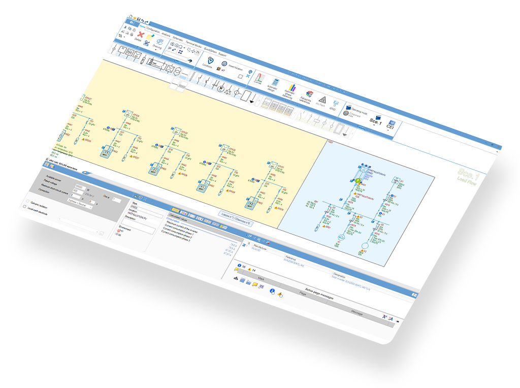
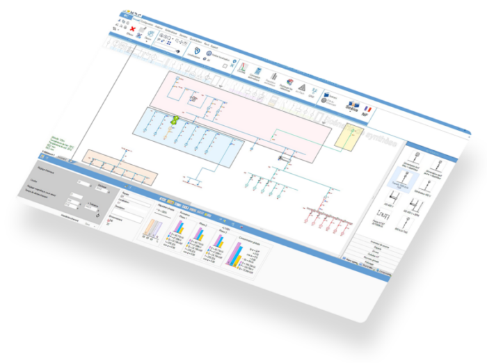
A suitable software must cover DC design according to IEC 60364-7-712 and AC electrical design within a single model. This is exactly the scope of elec calc SOLAR and the SOLAR module for elec calc.
IEC 60364-7-712 sets a maximum voltage drop below 3% (target value: 1%). The calculation includes short-circuit currents, circuit lengths, installation methods, and operating temperatures.
Sizing is carried out according to IEC 60364-7-712. It requires selecting appropriate surge protection devices and ensuring correct earthing of the installation.
A complete study covers DC sizing, AC network design, protection calculations, voltage drop verification, surge protection analysis, and grid connection. A unified software approach structures all these steps within a single project and automatically generates deliverables such as calculation reports, electrical diagrams, and material lists.
It eliminates duplicate data entry, ensures DC/AC consistency, automatically applies regulatory checks, and generates complete documentation from a single model. The result is fewer errors, faster studies, and easier project modifications during both design and operation.
Conclusion
The rapid growth of photovoltaic systems requires the ability to manage increasingly complex installations. Engineering firms, installers, and operators are all concerned. Solar generation must be integrated into existing electrical networks while meeting strict regulatory requirements and anticipating future site developments.
Unified photovoltaic sizing provides a structured response to these challenges. By modelling the entire project within a single calculation environment, this approach improves technical consistency and secures calculation results. It facilitates regulatory compliance and creates a long-term reference for system operation.
For industry professionals, it has become a key lever for improving project reliability, increasing productivity, and enhancing the overall technical quality of studies.
elec calc SOLAR is the Trace Software solution that implements this approach. Built on the proven elec calc calculation engine, it enables the design and sizing of a complete photovoltaic installation within a single project. Its scope covers everything from the DC field through to low-voltage loads, EV charging infrastructure, and grid connection. Compliance with IEC 60364-7-712 is ensured natively. For users of archelios PRO, direct import of PV system architecture eliminates the need for re-entry.
Certified ELIE BT 2025 and recognised by inspection bodies for the validation of electrical studies.
This article was written by :

Fabien LEROY
Product Expert - Trace Software
Beyond providing an increasingly comprehensive electrical calculation solution, we also aim to share our technical and industry expertise with stakeholders in the sector, in order to support them in sizing, validating, and ensuring the consistency of the generated calculation reports, thereby guaranteeing their accuracy and operational relevance.