


 Technical
Summary
A BESS (Battery Energy Storage System) is not a passive load: its bidirectional inverter (PCS) injects a limited but real fault current, with a different dynamic than range than a rotating source. Added to an existing installation, in particular with photovoltaics, it requires the short-circuit currents to be recalculated at any point in the network, not just at the connection point, otherwise the protections and cables downstream will be undersized.
A fast-growing market, driven by the need for network flexibility
Battery storage is changing scale in France. According to the technical sheet published by RTE in its Ten-Year Grid Development Plan, about 1 GW of stationary batteries are now connected to the French electricity grid, with an average power of 20 MW per site. RTE anticipates a modelling of 6 GW of additional batteries to meet the flexibility needs of the electricity system. In the longer term, RTE’s Energy Futures 2050 prospective study retains, depending on the scenarios envisaged, between 21 and 26 GW of battery storage capacity needed to support the ramp-up of intermittent renewable energies.
This growth has a direct consequence for installers and integrators: more and more BESS are being added to electrical installations already in operation, in particular tertiary or industrial photovoltaic power plants. This logic of a posteriori addition is precisely the one that calls into question the electrical protection plan. A protection scheme originally designed for a single source, the network, becomes obsolete as soon as a second active source changes the value of the fault currents.
At Trace Software, we have been supporting design offices and installers for several years on the sizing of low and high voltage installations with the elec calc range, as well as on photovoltaic sizing with the archelios range. This dual expertise, electrical and solar, puts the company in an ideal position to understand a subject at the crossroads of the two worlds: the contribution of the energy converters of the storage systems to the short-circuit currents of the installation.
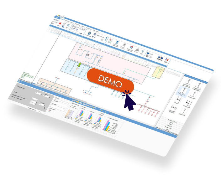
Are you integrating BESS into existing installations and want to check your protection devices?
An elec calc demonstration shows how this contribution is calculated.
The BESS, a useful reminder before addressing the issue of protection
What does BESS mean?
BESS stands for Battery Energy Storage System (BESS). It refers to a complete package combining a battery pack, a battery management system, a power conversion system and an energy management system, intended to store electricity for release at the most opportune time.
What are the activities of a BESS
A BESS performs several functions on an electrical installation. It stores surplus solar production to improve the rate of self-consumption. It caps the peaks of demand to reduce the power component of the network bill. It participates in system services with the network operator, such as the primary frequency reserve or demand response during national peaks, a role documented by RTE as part of the management of the supply-demand balance. It can also secure the power supply of critical loads in the event of a power outage. Each of these activities is based on the same technical brick, the PCS, which converts the direct current from the batteries into alternating current that can be injected into the grid, and vice versa.
Why is a PCS inverter not a passive source with regard to the short circuit?
This is where the most often neglected technical point lies. A design office that calculates the short-circuit currents of an installation reasons historically by taking into account the classic sources: the upstream network via the transformer, and possibly a generator or an alternator. These sources are rotating machines, whose behavior in the event of a fault is well known and widely documented in electrical calculation software.
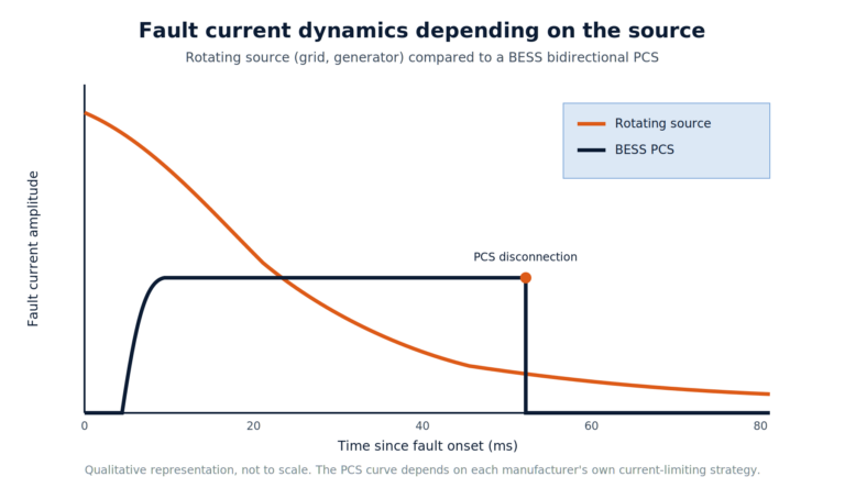
A two-way BESS Power Conversion System (PCS) does not fall into either of these two categories. Nor is it a purely passive charge that would disappear from the calculation. When a fault appears on the grid, the power electronics of the inverter continue, for a short time, to inject a fault current. This contribution is limited in amplitude, generally in the order of one or two times the nominal current of the inverter depending on the control technology used, which is still much lower than the contribution of a rotating source. But it is far from zero, and above all its dynamics differ fundamentally from that of a rotating machine. To better situate this contribution among the different types of fault currents, our article on the different types of short-circuit currents details the characteristic values to be aware of.
A rotating source delivers a fault current that gradually decreases according to a time constant related to its electromagnetic characteristics. A PCS, controlled by high-speed control electronics, reacts in a few milliseconds and can adopt a limited current behavior, almost constant over the duration of the fault, before its internal protection disconnects it. This difference in dynamics changes the way downstream protections must be coordinated with each other, particularly in terms of time and current selectivity.
IEC 60909, the International Electrotechnical Commission’s international reference for the calculation of short-circuit currents in three-phase networks, provides a framework for the general method of calculating the contributions of each source. Static sources such as BESS converters do not behave like the classical synchronous or asynchronous machines already covered for a long time by this standard, which requires special attention when modeling their contribution.
The risk of undersized protections when adding a BESS
The most common scenario in the field is that of a BESS added to an existing installation, often in addition to a photovoltaic power plant that is already connected. The installer or the design office that manages this project naturally checks the connection point of the BESS and ensures that the protections at this point hold the maximum expected short-circuit current. This verification is necessary, but it is not sufficient.
The problem is that adding an additional active source changes the value of the fault currents over the entire electrical installation, not just at the point where the BESS is connected. A fault occurring at a secondary switchboard, far from the BESS, will now see a current contribution from both the grid and the PCS. If the protections between this secondary panel and the BESS have not been recalculated with this additional contribution, two risks arise. The first is a circuit breaker or busbar failing to withstand the short-circuit current because it was not rated for this additional value. The second, often more insidious, is a loss of selectivity between upstream and downstream protection, which can lead to the tripping of a circuit breaker not affected by the fault rather than the nearest protection.
This risk is all the more real as the contribution of a PCS, although limited in amplitude, can be enough to tip over a protection setting that was based on already reduced safety margins, particularly on old tertiary installations where the protections have been sized as accurately as possible. The earthing scheme used on the installation also influences the way in which this risk manifests itself. Our article on the neutral regime details the specificities of the TN-C, TN-S, IT and TT to be taken into account during this type of integration.
Recalculate short-circuit currents at every point in the network, not just at the connection point
The rigorous method consists of taking the complete single-line diagram of the installation after the addition of the BESS and recalculating the short-circuit current at each node of the network, taking into account simultaneously the contribution of the upstream network and that of the PCS. This process involves several successive checks.
- Identify all potential points of fault between the BESS connection point and the consumption points, including those that appear to be far from storage.
- Model the contribution of the PCS with its real current limiting curve, provided by the converter manufacturer, rather than equating it with a conventional rotating source or simply ignoring it.
- Recalculate the required breaking capacity for each circuit breaker located downstream of the BESS injection point.
- Recheck the selectivity between upstream and downstream protection throughout the chain, taking into account the specific response time of the PCS.
- Recheck that the thermal withstand capacity of the cables is still sufficient with regard to the calculated thermal stress.
- Document the results in an updated calculation note, enforceable in the event of an audit or claim.
This approach requires a short-circuit calculation tool capable of natively considering the contribution of a BESS PCS, and not only the classical sources. This is precisely where most software on the market shows its limits.
Case study: 800 kWh tertiary BESS added to an existing PV system
Let’s take the representative case of a tertiary building equipped with a photovoltaic power plant on the roof, connected to the general low-voltage switchboard for several years. The site manager decided to add a BESS of 800 kWh to shave off the power peaks and recover part of the solar production that was not self-consumed. The BESS is connected to the same main panel as the PV plant.
At the time of installation, the BESS connection point is correctly checked: the protections at this point hold the combined contribution of the grid, the PV inverter and the BESS PCS. On the other hand, the secondary switchboards located downstream, which supply the different floors of the building, have not been recalculated, as they had already been validated during the initial installation of the photovoltaics, without storage.
A complete recalculation, including the contribution of the PCS at any point in the network, reveals that one of the secondary switchboards, already close to its holding limit with the contribution of the network and the PV alone, slightly exceeds the maintenance threshold of its circuit breaker once the BESS contribution is added. The safety margin that existed before the storage facility was installed has disappeared. This type of situation cannot be detected by limiting yourself to the BESS connection point. It only appears by repeating the short-circuit calculation over the entire electrical tree of the building.
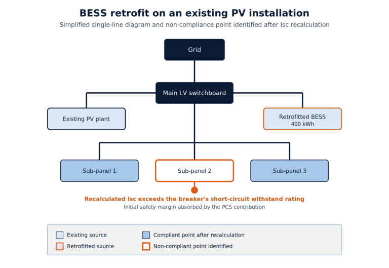
This case illustrates why the verification of the single connection point, as rigorous as it is, does not protect against a drift in the coordination of protections elsewhere on the installation.
A BESS project in progress and a doubt about the strength of your existing protections or the thermal withstand capacity of the cables? It is possible to test this scenario directly with elec calc during a personalized demonstration.
Securing the coordination of protection after integration of a BESS: the installer's checklist
Before commissioning a BESS on an existing installation, a few checks can prevent the majority of incidents related to poor coordination of protections. These points are also in line with several errors identified in our article on frequent errors in flash arc studies, a subject directly related to the accuracy of the short-circuit calculation.
- Verify that the calculation tool used incorporates the specific Icc contribution of the PCS, with its own limitation curve, and not an approximation based on a rotating source.
- Repeat the complete post-BESS single-line diagram and recalculate the Icc at each switchboard, each start, each busbar and each cable located between the injection point and the loads.
- Check the breaking capacity of each circuit breaker subject to the short-corcuit currents ( Icc) of the installation, including switchboards that have not been physically modified by the work.
- Ensure that the thermal withstand capacity of the cables is checked by taking into account short-circuit currents in the thermal stress calculation.
- Revalidate the time and current selectivity between upstream and downstream protection, taking into account the reaction time specific to the PCS.
- Produce an updated calculation note incorporating the BESS contribution, dated and kept with the installation’s technical file.
Historical short-circuit calculation software for the electricity market efficiently processes conventional sources such as the grid, generators and alternators. The specific contribution of a BESS PCS, with its own dynamics and its current limitation curve, remains little or poorly supported by the majority of tools currently used by design offices.
The calculation engine of the elec calc software has been built to natively integrate this contribution into the overall calculation of short-circuit currents, taking into account the real behavior of bidirectional storage converters alongside conventional sources.
For a BESS installer or integrator, this means having a reliable short-circuit calculation over the entire installation after adding storage, without having to approximate or neglect the contribution of the PCS. In a market where the addition of BESS to existing installations is becoming a common practice, this design capability is a differentiating technical benchmark, both for the compliance of the electrical file and for the operator’s peace of mind.
FAQ
BESS is the acronym for Battery Energy Storage System, a complete system combining batteries, bidirectional charger, management system and protection, intended to store electricity for later release.
A BESS stores surplus renewable generation, caps power peaks, participates in system services with the grid operator, and can secure the supply of critical loads in the event of a power outage.
Yes. The contribution of the PCS changes the value of the fault currents on the entire electrical installation concerned, not only at the connection point, which makes it necessary to completely recalculate the coordination of the protections.
Its contribution in amplitude remains limited compared to a rotating source, but it is added to that of the network and can tip over an already reduced safety margin, in particular on older installations designed with minimal safety margins.
What you need to remember
The addition of a BESS to an existing installation is never a neutral operation for the electrical protection plan. The bidirectional PCS injects a limited but real fault current contribution, with dynamics that differ from a rotating source. Limiting oneself to checking the connection point exposes the downstream protection to an undersizing, as illustrated by the case of a 400 kWh tertiary BESS added to an existing photovoltaic installation. The only reliable method is to recalculate the short-circuit currents at any point in the network and to revalidate the selectivity of the protections with a tool capable of natively taking into account the contribution of a BESS PCS.
To check the performance of your protections and cables on your next BESS integration projects, a demonstration of elec calc allows you to evaluate this approach on a real case.
This article was written by :

Fabien LEROY
Product Expert - Trace Software
Beyond providing an increasingly comprehensive electrical calculation solution, we also aim to share our technical and industry expertise with stakeholders in the sector, in order to support them in sizing, validating, and ensuring the consistency of the generated calculation reports, thereby guaranteeing their accuracy and operational relevance.


