The sizing of electrical cables is a crucial step in guaranteeing the safety and performance of an electrical installation. Incorrect cable selection can lead to excessive heating, energy losses or premature network degradation.
For the determination of an active conductor’s cross-section, several factors must be considered:
- Verification of the ampacity current in steady state
- Voltage drop
- Verification of thermal stress resistance
The design current
In the most common case where the cable is protected by an overload protection device, the following conditions must be met
- The ampacity of the pipeline (Iz) is higher than the rated current (In) or the control current (Ir) of the protection
- Conventional protection trip current (I2) is less than (1.45 x Iz)
This translates to circuit breaker protection by: Iz ≥ In
and for gG/gM fuse protection by:
- if In ≤ 4 A then Iz ≥ 1.45 x In
- if 4A < In < 16 A then Iz ≥ 1.31 x In
- if In ≥ 16 A then Iz ≥ 1.10 x In
Determination of steady-state ampacity
Among the intrinsic characteristics of a cable or conductor, the one that makes it possible to calculate its ampacity is the maximum steady state core temperature.
Because of their impedance, the heat in the conductive cores that is produced by a passing current, the Joule effect, dissipates through the various insulating outer layers by conduction and is eventually evacuated to the environment outside the cable, either by convection or by conduction.
When the heat losses are equal to those dissipated in the ambient environment, an equilibrium state is established, characterized by a steady-state core temperature. To guarantee the cable’s lifespan, the steady-state core temperature must not exceed the insulation’s maximum temperature resistance.
The maximum permissible steady-state current is thus the current that causes the conductors to heat up to the maximum permissible value for a defined environment.
The IEC 60287 series of standards specifies the calculation methods for determining the permissible conductor currents according to their environment. However, the complexity of this series of standards makes it impractical for the designer who may have to size a large quantity of these cables when studying a low voltage electrical installation.
Fortunately, regulators have introduced typical installation methods into the standards relating to LV installations (IEC 60364-5-52 or the national versions) that make it easier to determine the permissible currents from the following elements, which will be detailed in the following paragraphs:
- The type of cable or conductor
- The installation method
- The reference installation method
- Correction factors related to the installation method
- The rate of harmonics circulating in the neutral
Types of cables and conductors
Nature of the Soul of Conductors
The resistivity, i.e. the resistance of a conductor, depends on the nature of the core. In practice, the following materials are considered in the standards:
- Annealed, bare or metal-coated copper
- Aluminium or aluminium alloy
The cores can be massive or wired. The IEC 60228 standard specifies the construction limits and resistance characteristics.
In practice, the resistivity values at 20°C (ρ0) used in the calculations are as follows:
| Copper | Aluminium | |
| ρ0 en mΩ.mm2/m | 18,51 | 29,41 |
The resistivities at other temperatures are given by the following formula:
![]()
Nature of conductor insulation
The nature of the conductor insulation will determine the web’s maximum steady state temperature. The two main families of insulation used in practice are the following:
- Thermoplastics (PVC) with a maximum steady-state core temperature of 70°C.
- Thermosets (rubber, XLPE or EPR) with a maximum steady-state core temperature of 90°C.
Single-core, multi-core, and insulated conductor cables
Since the ampacity depends on a thermal balance between the conductor’s core and its environment, it goes without saying that the cable’s construction will influence its calculation.
It is therefore necessary to specify the type of cable used:
Insulated conductor: it consists of a core, an insulating envelope and any screens. It cannot be used as an active conductor without additional mechanical protection (duct, chute, moulding, etc.).
Wire: an assembly consisting of one or more insulated conductors, any individual coating thereof, any assembly protection and any protective coating(s) or sheathing. It can be used without additional mechanical protection. A distinction can be made between:
- Multicore cables: comprising several insulated conductors
- Single-core cables: comprising a single insulated conductor. In this case, it must be specified whether the cables of the same circuit are laid in clover or in a ribbon.
Number of conductors loaded
The number of conductors charged will of course influence the cable’s thermal balance. The number of conductors to be considered in a circuit is the number of conductors actually traversed by the current.
When in a polyphase circuit the currents can be assumed to be balanced, the corresponding neutral conductor does not need to be taken into account.
Thus, under these conditions, the ampacity in a four-conductor cable is the same as for a three-conductor cable of the same cross-section.
Installation methods and reference methods
In this paragraph, reference is made to IEC 60364-5-52. The national variations may be slightly different, but the principle of determining the permissible intensity is the same.
Appendix A of this standard (Table A.52.3) presents about fifty standard installation methods numbered between 1 and 73. These laying methods refer to reference installation methods (or reference methods) for which the ampacity has been determined by tests or calculation: A1, A2, B1, B2, C, D1, D2, E, F and G.
Extract from the table of installation methods and reference installation method (A.52.3 of IEC 60364-5-52):
Correction factors
The ampacity values in the table above are valid for a single pipeline under given air or ground temperature conditions. As far as thermal equilibrium is concerned, it is obvious that the real value of the permissible current will be affected if several pipes are in the vicinity of each other and if the temperature conditions are different.
It is therefore necessary to apply correction coefficients to the values in the tables of the standard to take these factors into account.
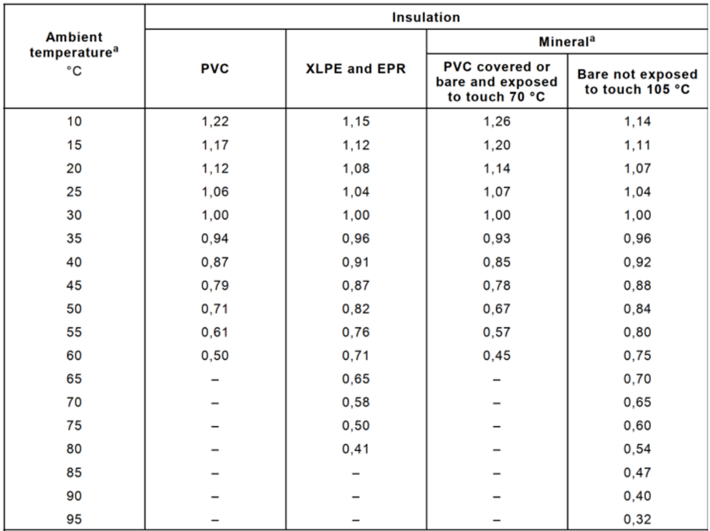
Air temperature
For cables laid in the open (all reference methods except D1 and D2), the correction factor to be applied to the ampacity current values for ambient temperatures other than 30°C is as follows (B.52.14 of IEC 60364-5-52): :

Soil temperature and resistivity
For buried cables (reference methods D1 and D2), the correction factor to be applied to the permissible current values for ground temperatures other than 20°C is as follows (B.52.15 of IEC 60364-5-5-52):

For buried cables, heat dissipation also depends on the thermal resistivity of the soil. The correction factor to be applied to the permissible current values for soils with a thermal resistivity other than 2.5 K.m/W is as follows (B.52.16 of IEC 60364-5-52):

Trunk grouping
The ampacity given in the tables is applicable to simple circuits.
If more conductors or cables are installed in the same group, different correction factors must be applied depending on the reference method. As an example, the following table (B.52.21 of IEC 60364-5-52) gives the correction factor for reference method F (single-core cables on perforated shelves or cable ladders). It will be noted that different cable arrangements (laying in a ribbon or in a clover for the same circuit) give different values:
It should be noted that if the current likely to flow through an insulated cable or conductor is less than 30% of the ampacity current, the cable or conductor may be omitted when calculating the correction factor of the group.
Why use elec calc for electrical cable sizing?
Optimising the sizing of electrical cables is a complex task, requiring accurate and standard-compliant calculations.
elec calc offers a high-performance solution that allows:
- Real-time installation variations to be taken into account.
- Considerable time savings with automating calculations
- Compliance with NF C 15-100 and IEC 60364-5-52 standards
- Clear visualisation of constraints to avoid errors
- Guaranteed sizing optimisation
- A detailed compliance report with all the project assumptions
With elec calc, electrical engineers optimise the reliability and safety of their systems.
Conclusion
The sizing of electrical cables is a major challenge in ensuring the performance and safety of an electrical installation. Taking into account variations in installation conditions, applying correction coefficients and using automated calculation software such as elec calc allows you to optimise the electrical design.
Need a powerful tool for your electrical studies?
Test elec calc now and ensure the compliance of your installations
This article was written by:
Jérôme MULLIE
Technical Director - Trace Software
In addition to providing a complete calculation solution, we also want to share our expertise in electrical engineering with the players in the sector in order to support them in the design and operation of their installations.